
Skipper manufactures the entire range of products required in a HV substation namely: Transformers, Circuit breakers, CTs, PTs, Isolators and HT and LT Control and Relay Panels.
We also manufacture special duty products namely:
Rectifier Transformers, Furnace transformers, Earthing transformer and distribution transformer using CRGO steel or Amorphous steel.
All products are, at present, meant for LV and HV applications. A newly-built, modern plant is under construction at Bhiwadi India for manufacture of products in Extra High voltage classes, on a plot of Land measuring 40,000 sq. m.
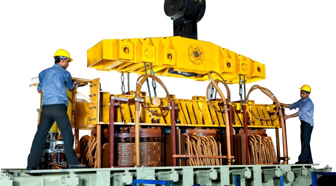
Manufacture and Type Testing of Power Transformer
Skipper secured an order for a turnkey project at Gurada in Nigeria. Supply, erection and commissioning of 2 Nos. 60 MVA transformers as per specifications given hereunder was included in the awarded contract.
Rating : 40/50/60 MVA
Cooling : ONAN/ONAF/ONAF, Vector Group :
Voltage Ratio : 132/34.5 kV
Taps : on HV for Variation of HV Voltage
The Challenge
The application of the transformer is to evacuate power from a gas/hydro generating station for local distribution load at 33kV which calls for a very sturdy and reliable design of transformer. The client expectation was to supply the product duly type-tested for a high fault current capacity with a high operating reliability.
Important aspects of Design

The design has to provide for
• adequate dielectric strength,
• adequate SC strength, and
• adequate thermal ability,
• taking into consideration challenges imposed by local & climactic conditions (temperature, humidity etc.)
Most common arrangement and type of coils
The arrangement of coils most commonly employed for this specification of design is :
• LV (double disc type) as innermost coil concentric with limb
• HV (interleaved / partially interleaved type), 2 coils in parallel with main lead at the centre
• Regulating (discs type), 2 coils in parallel, placed outermost
Main lead take-out poses some threats to dielectric design. Also the SC strength suffers due to axial gap in regulating winding.
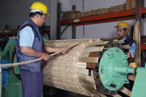
- Winding process

Skipper’s Choice of Position of Regulating Winding
We chose the following coil positions :
LV : Double disc type as innermost coil concentric with limb
Regulating : Multi-start spiral concentrically placed between LV and HV
HV (interleaved), 2 coils in parallel with main lead in centre
No other factor influences the overall strength of transformer as much as the choice of position of the regulating winding viz. a viz. HV and LV windings.
The multi-start regulating winding placed concentrically between LV and HV offers the best dielectric and the highest SC strength. However, since this winding is placed in high leakage field, it results in high eddy losses. This was taken care of through the use of CTC.
Design Verification/Review of Design : This was carried out as per plan.
Emphasis on QC : This was carried out religiously at all stages of production right from selection
of Vendors.
Commitment to Set Goals
Executives staff and employees were fully committed to see by body during the all process of design and manufacture. There was no hesitation in stepping back to see if the process was carried out as planned.
Satisfaction of Achievement
When the unit passed all the Routine, Type and Special tests, the satisfaction of Skipperites surely surpassed any physical award. These transformers are successfully installed on site to the complete satisfaction of the client.
